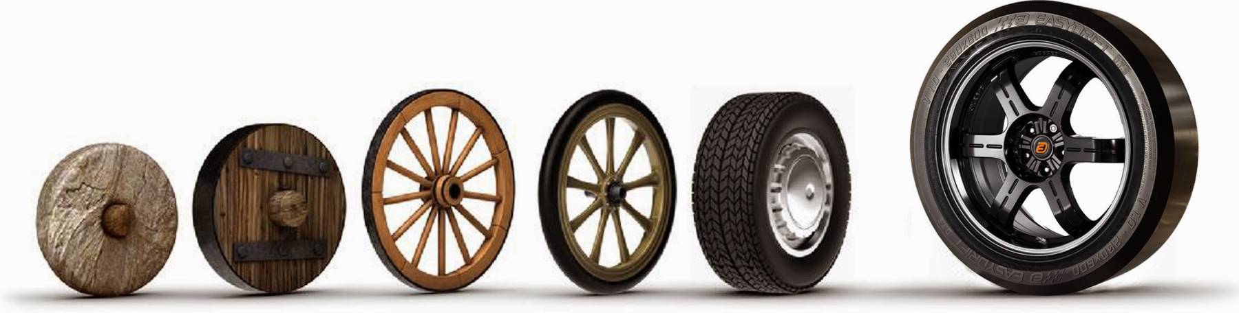
The Evolution of Engine Machining
Whilst the principles of engine machining have not changed significantly over the years, the methods employed and the machinery used to achieve the best engine machining finish have advanced as technology has improved.
The early beginnings of the modern combustion engine were developed during the late 1800's. During the past century since then, there has been significant development in engine design. Engines have undergone refinement to increase efficiency, reliability and production economy. Despite these developments, it still remains that engine components wear and machining is required when the engine is being reconditioned. Whilst the principles of engine machining have not changed significantly, the methods employed and the machinery used to achieve the best engine machining finish have advanced as technology has improved.
EXTERNAL INFLUENCES
As with many industries, engine reconditioning has been influenced by external factors. The availability of parts due to cost restraints has been a major factor when rebuilding engines. In the early era of engine design, right through to the 1980's, components and parts were far too expensive to replace. Components such as valves and pistons were commonly reconditioned, rather than having new replacements installed.
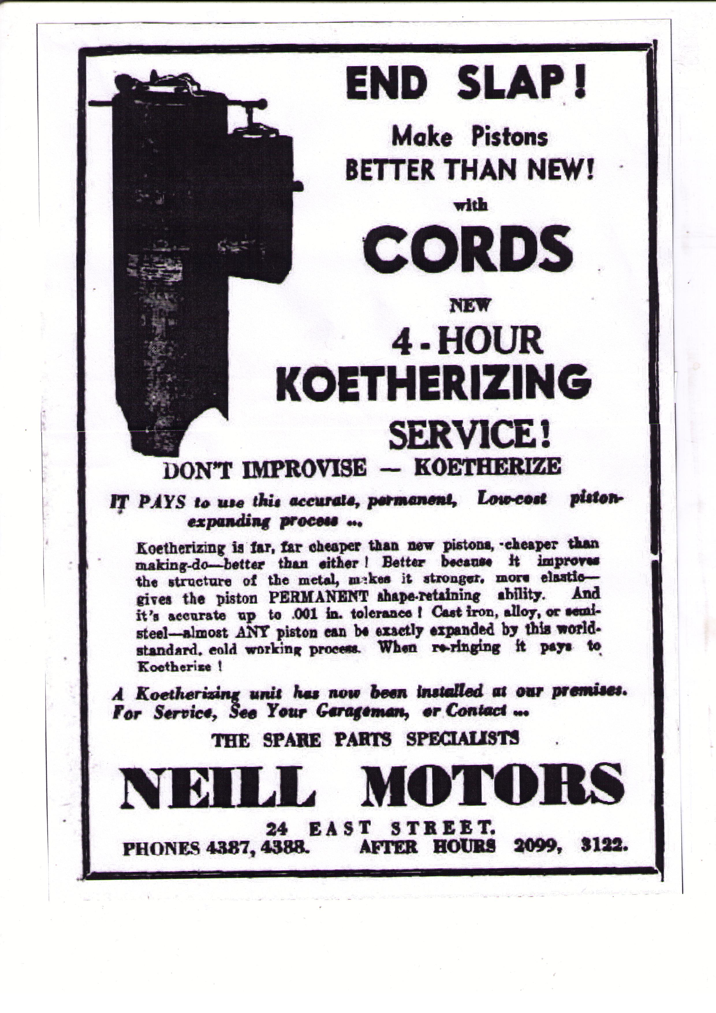
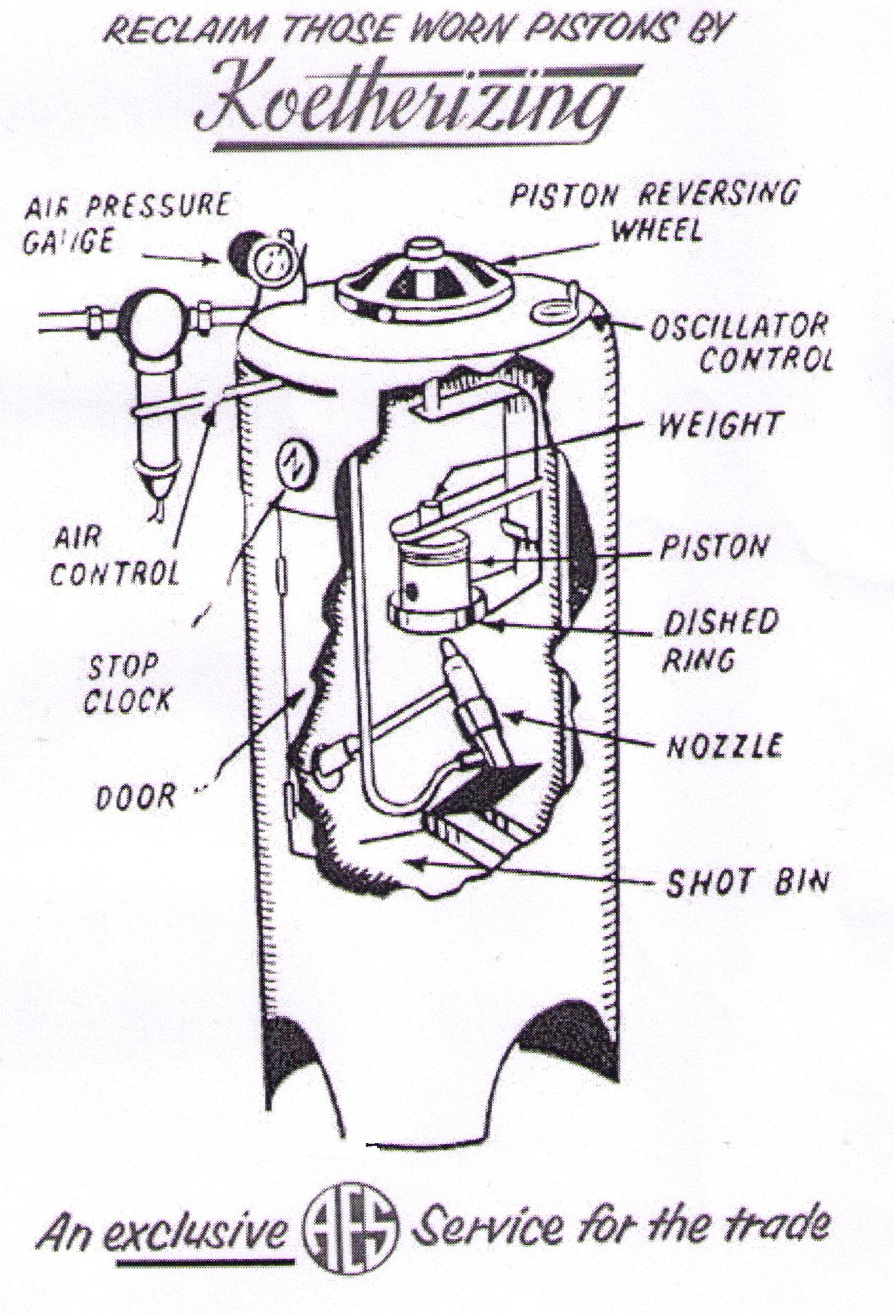
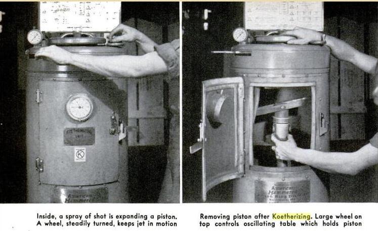
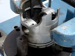
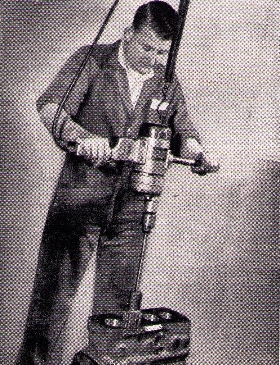
Using Koetherizing to repair old pistons....
 |
 |
 |
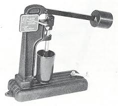
The advert displayed here was published in 1954.
Koetherizing was a method used to restore pistons to their original size by using a blast of compressed air to spray a steel shot inside the piston skirt. Worn pistons were first measured to determine how much expansion was required, and then placed in the "Koetherizing" machine. A timer on the machine tells the operator when the proper amount of spray has been applied. The piston is mounted to an oscillating table which the operator turns during the process to provide a proper distribution of pressure on the piston.
Back in the early days, piston rings were commonly supplied with a top piston ring spacer, which acted to take up the excess clearance in a worn ring groove. With some simple machining, the spacer would take up the space to repair the worn ring groove. New pistons were not required.
 |
 |
Of course, as technology improved, so did the efficiency of the production of parts. The introduction of NC and CNC technology revolutionalised the industry. The production of parts became far more cost effective as the time taken to produce a part became a fraction of the time previous taken to produce that part in the past. The price of new parts has reduced in-line with this production efficiency. As new parts become more affordable, reconditioning certain components has become obsolete.
Over the years, engine machining equipment has been upgraded and improved as the advancement of technology has provided better solutions for achieving the perfect machined finish.
The following provides an account of how machines have evolved in specific areas of engine machining…
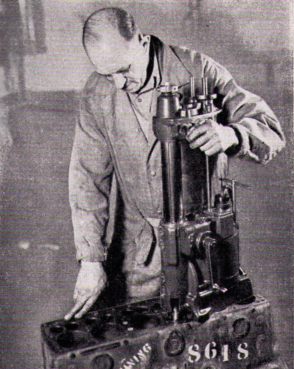 |
Some of the first portable cylinder boring machines, for reconditioning engine cylinders, were introduced in the early 1930's. | |
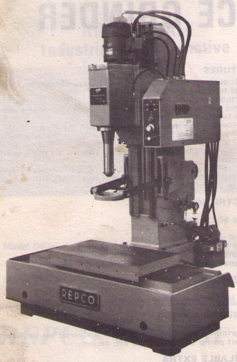 |
The B4B was a revolutionary machine in it's day and paved the way to a new era in cylinder boring. This machine allowed semi-automatic operation as the machine was programable. It featured an air float table, air-clamping, adjustable boring range and cutter speeds, variable feed rate and jigs to roll V6 and V8 engines. |
|
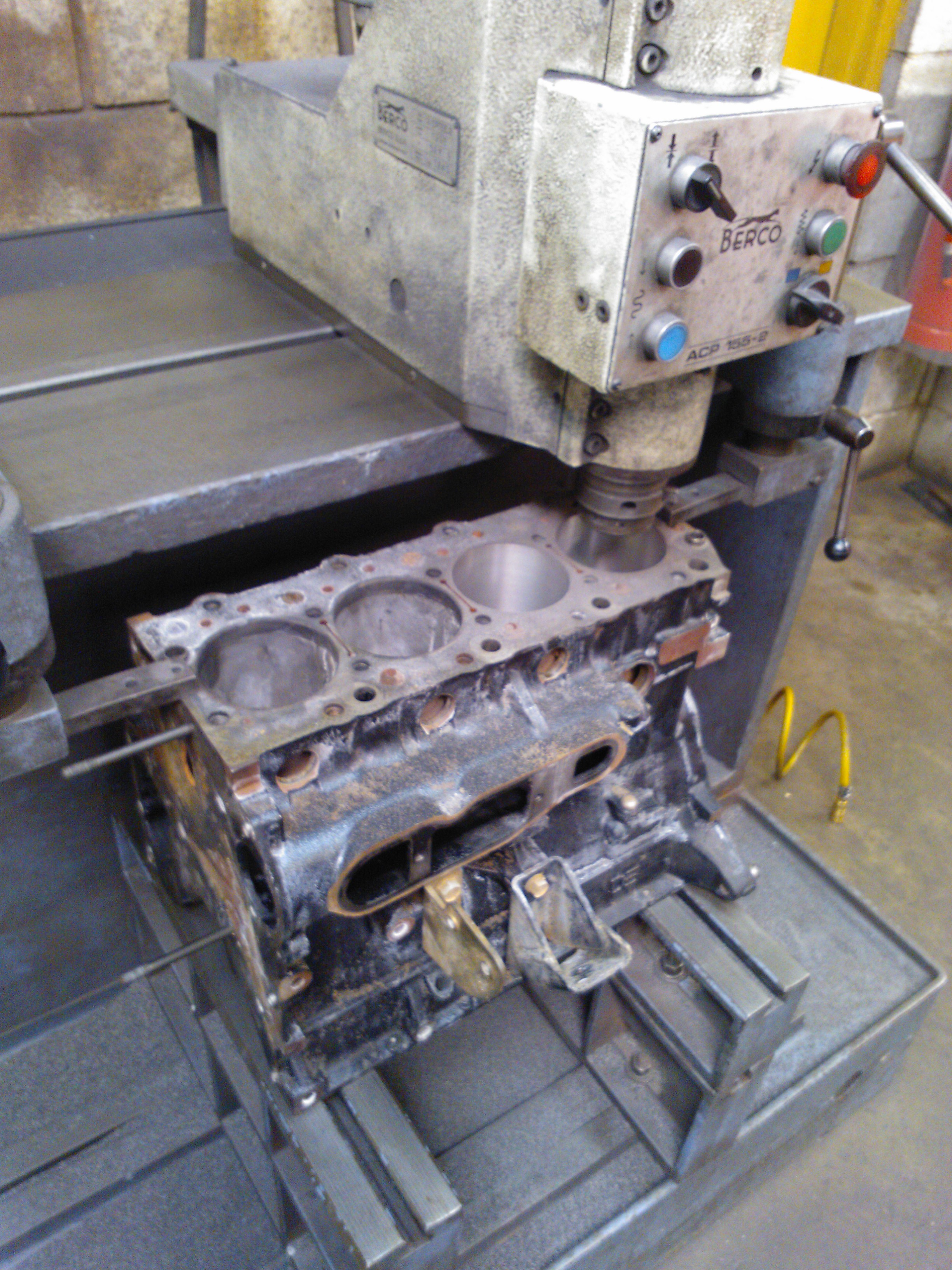 |
The next generation in cylinder boring machining. While the Repco B4B had a fixed head and with a moveable bed, this design was more user friendly and allowed quicker operation as the head moved with the bed remaining fixed. | |
|
|
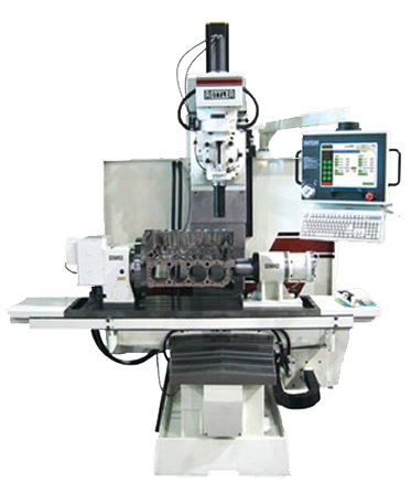
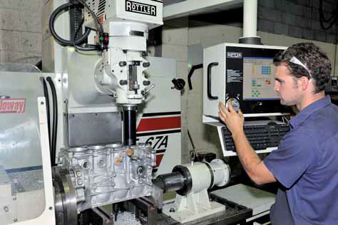
The Rottler F67A CNC Machining Centre employs the latest technology to perform block and bore modications and other blueprinting operations. |
 |
These honing machines, which were essentially drills suspended from overhead, could produce a poor finish as the operator had to watch for uneven stroking which could create a taper. The introduction of semi-automatic machines reduced this margin for error. |
|
 |
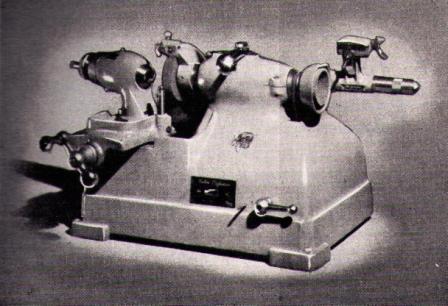
The Repco H3 Honing Machine was released during the same era as the Repco B4B Boring Machine, and featured the new "air-float" table and air clamping technology. |
|
 |
As with the next step in the evolution of the boring machine, the honing machine moved forward from the fixed head with moveable bed styled machine, to a design which used a moveable head, which was quicker in operation. |
|
Valve Facing began with hand-operated valve refacing machines. |
|
 |
Mechanical machines were obviously quicker and less labour intensive than hand operated tools. |
|
 |
Valve facing machines evolved to face angles with greater precision and less effort. |
|
|
|
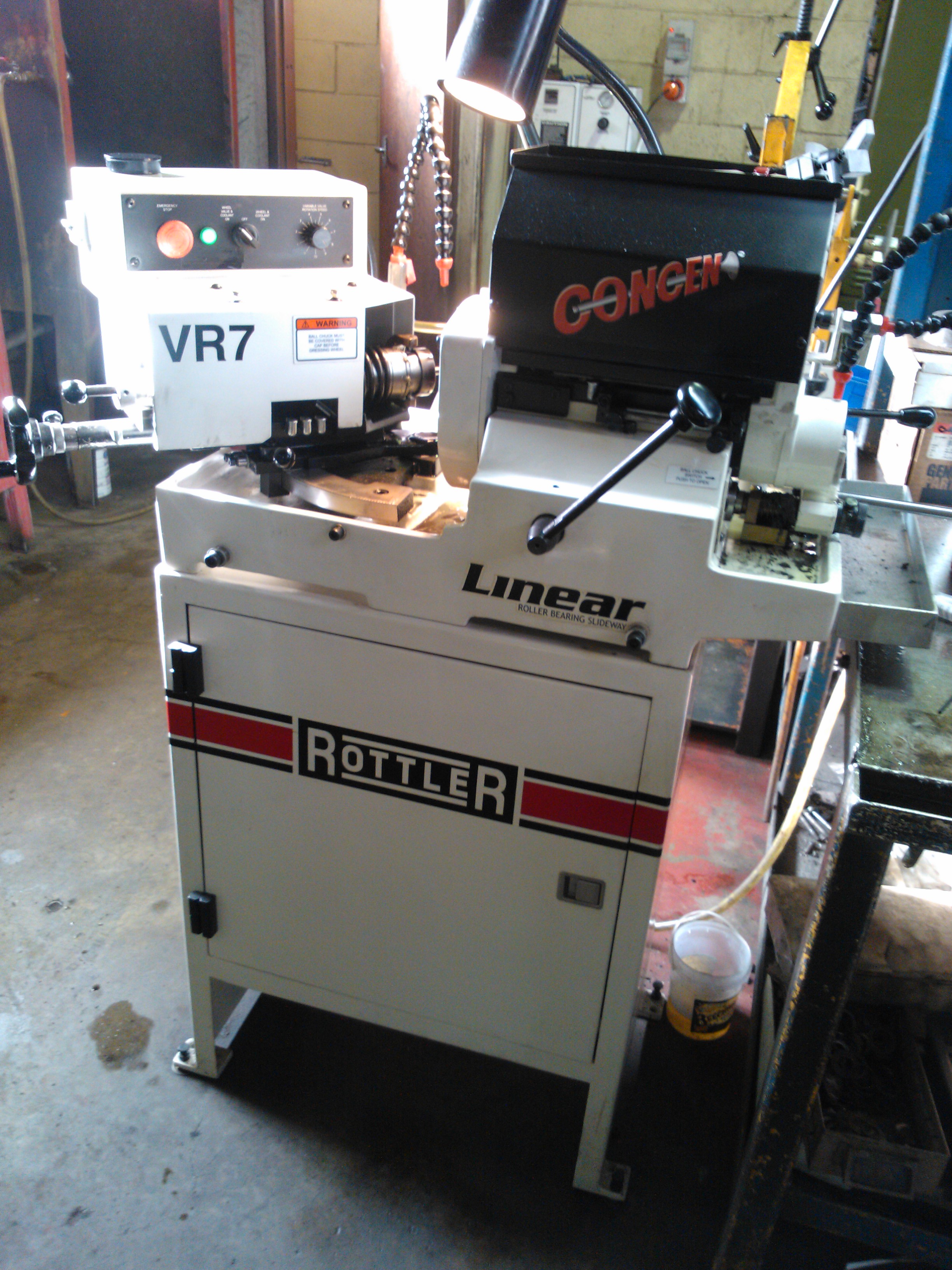
The Rottler VR7 Valve Refacing Machine sets new standards in speed and accuracy for cylinder head work. |
VALVE SEATS, INSERTS & GUIDES
|
|
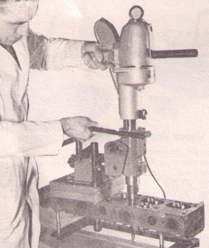
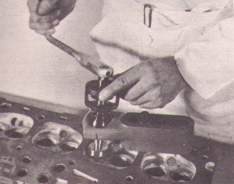
Valve seats were initially cut using a hand operated tool. The head of the Anchor swivels on a universal ball to align with valve guides at any angle to the face of the head. The cutters were chosen according to the size of the valve seat/insert. |
|
 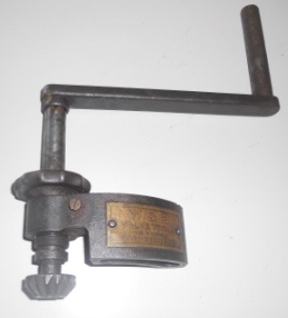 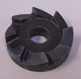 |
These tools were used by Laurie when he first began reconditioning engines back in the 1970's. The tapered cutter (pictured on the tool) was used for cutting seats, while the square-styled cutter was used for inserts. |
|
 |
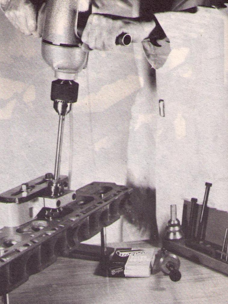
This machine was one of the first motorised units for insert recessing. The base unit was clamped to the head and the angle was adjustable to align with straight or inclined valve guides. |
|
 |
This tool was used for the insertion of thin wall valve guides. |
|
 |
The Repco RVR revolutionalised the machining of cylinder heads. This one machine was able to cut valve seat recesses, drill and ream for thin wall guides, ream valve guides and cut, throat and narrow valve seats. This increased the speed and efficiency of these operations. |
|
 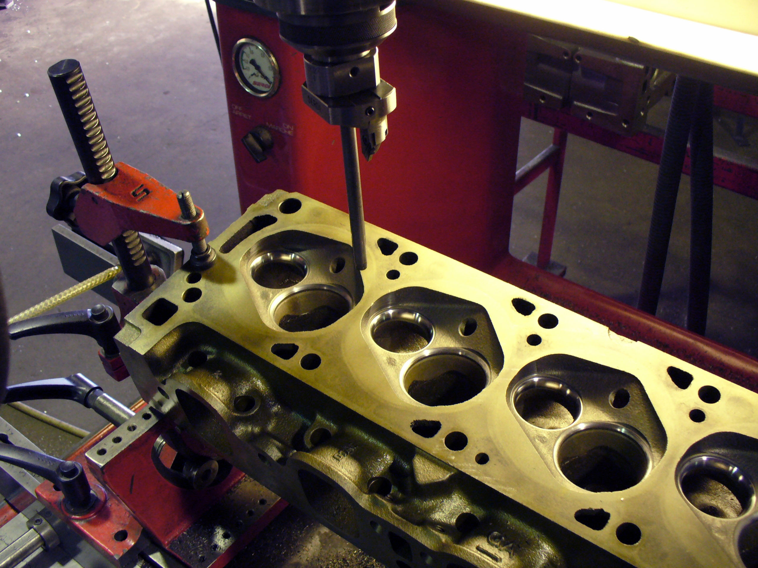 |
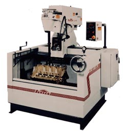
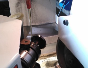
Our Serdi 3.0 valve seat machine is highly regarded as the most accurate for precision valve seat machining. |
|
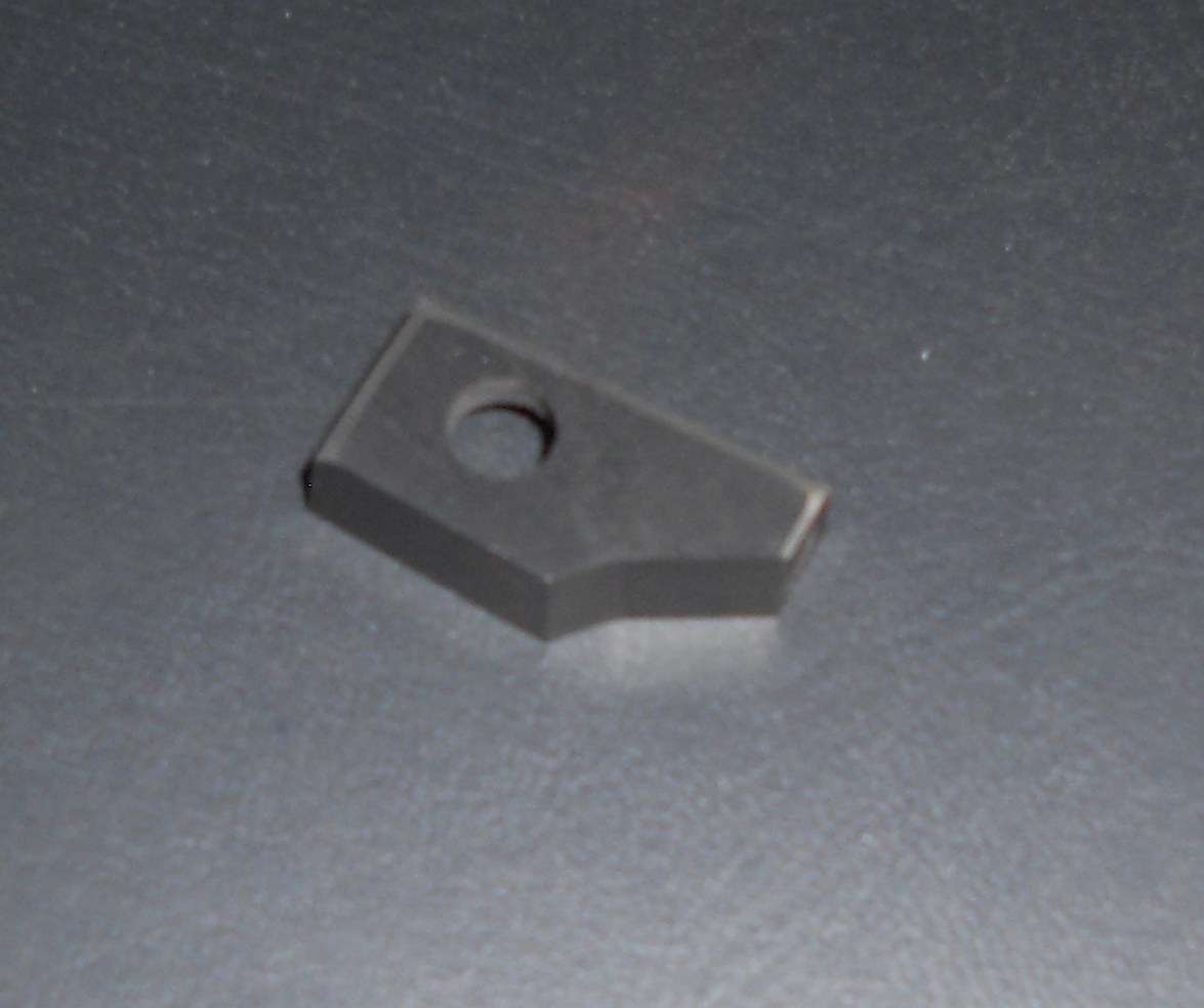 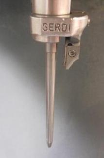 |
The cutters on the Serdi vary significantly to the cutters used on the hand operated tools. The second picture shows the cutter on the machine with the guide probe. |
COST FACTORS
While engine balancing technology was available to vehicle manufacturers, the average machine shop could not afford this level of investment, unless it was justified with demand. Balancing machines were not introduced into many engine reconditioning workshops, as balancing was only used in performance or racing applications.
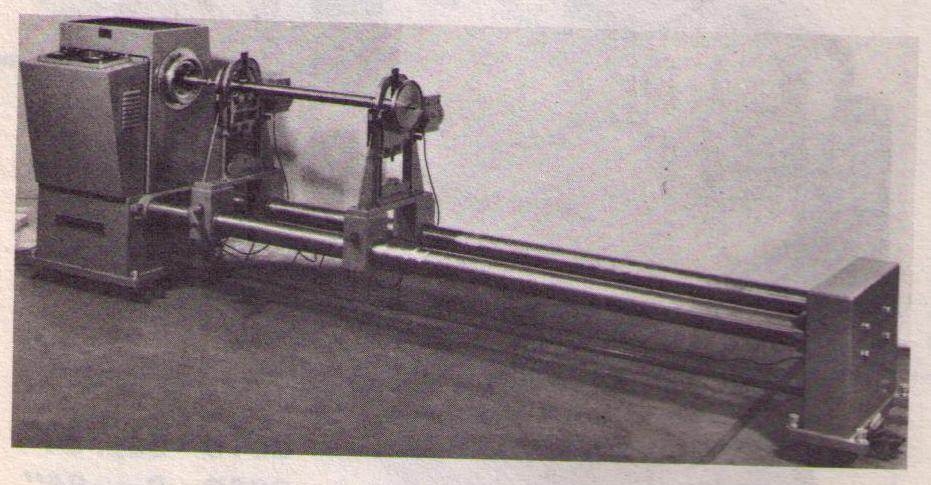
Universal Balancing Machines were introduced into crankshaft production lines. Balancing lines for cranshafts determined the unbalance of the crankshaft and the required drilling depth for its correction. A simple transport system transferred the crankshaft from the measuring station to the drilling unit and back.
It wasn't until the early 1950's when a new method was developed for large volume production of crankshafts. This new process enabled the actual axis of inertia of a crankshaft forging or casting to be determined and marked with centering holes. Mass correction was performed by a drill unit integrated into the balancing machine. The cost of balancing became much more economical as removal from the balancing machine and re-installing on the drilling machine was no longer necessary.
The next major influence on engine balancing came with the introduction of electronic technology in the 1970's.
Repco DB1 Electronic Balancing Machine
This developed further with the emergence of microprocessors in measuring systems in the 1980's and digital technology was introduced into the balancing process.

The CWT Multi-Bal 5000 offers state-of-the-art analysing electronics which allows our machine to give extremely fast and accurate analysis of a crankshaft or rotating part. This allows "real time" updating of the correction requirements. The control software allows us to accurately correct the unbalanced crankshaft and offers unlimited data storage for bob-weight information, part numbers and part description.
Balancing a crankshaft is now more affordable with the efficiency of the CWT Mult-Bal 5000. A service which was once only seen in vehicle manufacturing production lines or large industrial workshops and offered only to large budget race teams, is now available for all engines, whether it be a performance, restoration, heavy duty or everyday application.
Galloway Engines have followed the evolution of engine machining since 1978. Our continuous equipment update policy ensures we are at the forefront of engine machining technology. Although our policy can be expensive, it runs in line with our desire to be the best and ensures our customers get the best engine machining available.
This enthusiam in the industry extends beyond the workshop. Laurie is a keen collector of engine reconditioning memorabilia and his interest has initiated the set-up of a collection of old machining equipment.


