Crankshaft Balancing
There is a lot of science, and a little art too, involved in correctly balancing a crankshaft. The results of not balancing a crankshaft to the correct tolerances can be catastrophic, so read and pay heed.
Factory crankshafts are balanced before they find their way into your stock engine but they are done so too much greater tolerances than would be acceptable in a performance engine, simply because a stock engine is limited by many mass production compromises and are not designed to see high rpm use. It is the combination of high revs and the degreee of imbalance that result in vibrations and harmonics within the engine (often undectected) that are quite capable of cracking crankshafts, breaking webbing in the block and hammering bearings until they resemble gold leaf. Apart from the destructive capabilities of these forces resulting from unbalanced mass, they are also responsible for parasitic losses that reduce the available power at the flywheel.
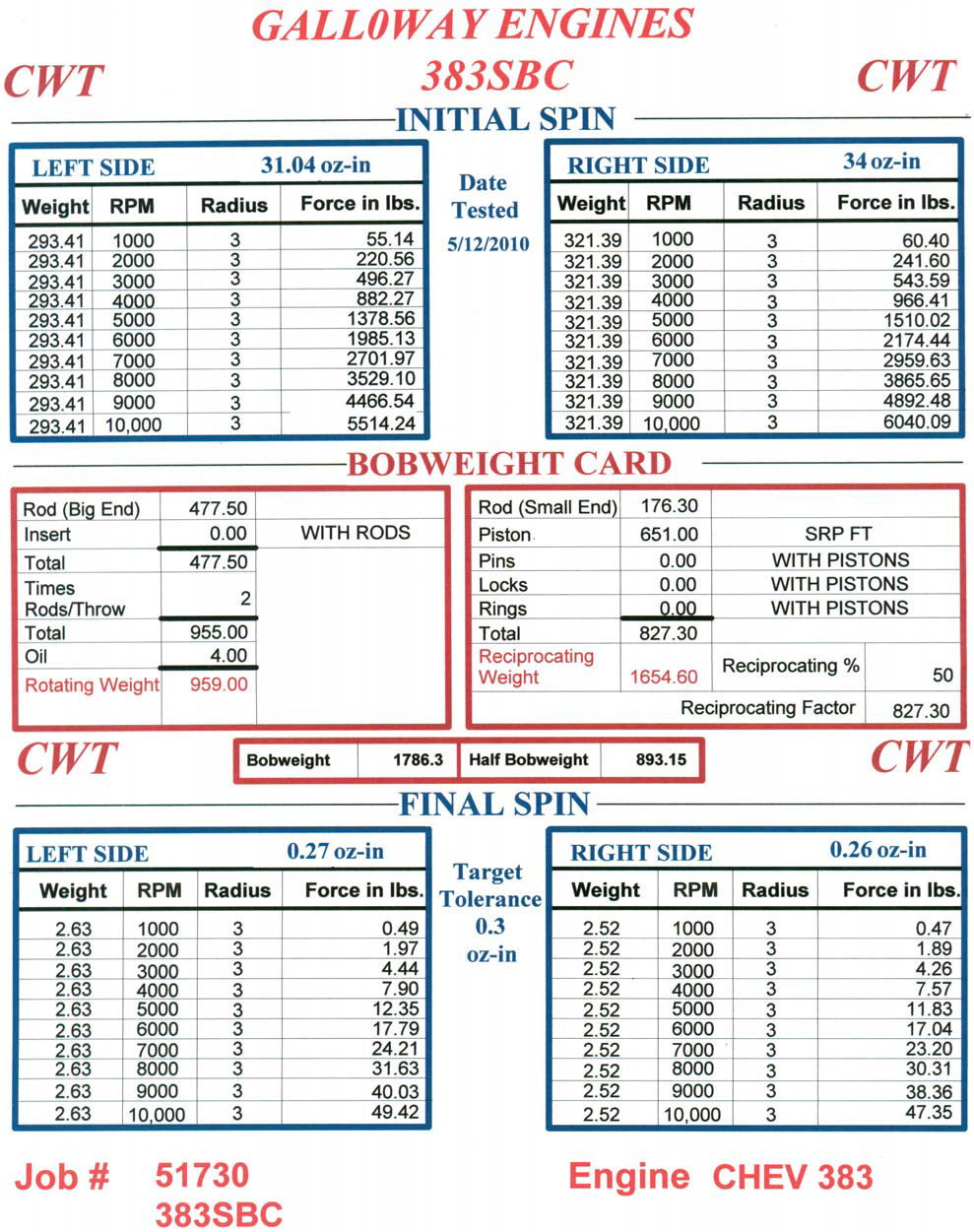
To put things into perspective, let us consider the exact degree of the forces at work. Let us consider an extreme example (but a real world example nonetheless). A 383 Chev engine was assembled and run with an unbalanced crankshaft; it was 293.41 grams out of balance at the rear and 321.39 grams out at the front. At 1000 rpm, that amount of weight at the rear of the crank is generating 55.14 lbs of unbalanced force within the crankshaft. That is, it is hammering the bearing with a force of just over 55 pounds - that is just at idle. Now let's up the ante and raise the revs to 6000. At this rpm level that force has grown exponentially to a staggering 1985.13 pounds! That is nearly one metric Tonne of force hitting the bearing 100 times per second. This is from a 293 gram weight rotating 3-inches from the centreline of the crankshaft.
This occurs from a basic principle of physics - that when dealing with rotating mass, if you double the speed, your quadruple the force generated. So, it is easy to see how quickly that force can become huge. With careful balancing, the forces present in a street engine at 6000 rpm can be brought down to as little as 17lbs with a tolerance of less than 0.3 ounce-inches. With a lot more time invested at the balancing machine, a full race crankshaft can be balanced down to a minute 0.2 grams and that reduces the force at 6000 rpm to a negligible 1.35 pounds (it only generates 3.75 pounds at 10,000 rpm).
Preparation Before Crankshaft Balancing.
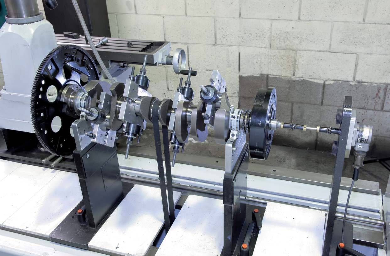
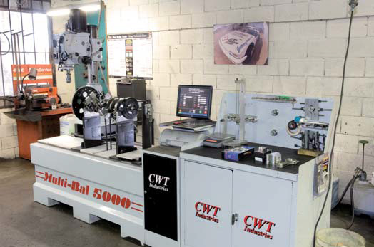
To find out exactly what is required to balance a crank to these fine tolerances, we journeyed to Pinjarra to visit Laurie, David and the team at Galloway Engines. They have the only CWT Multi-Bal 5000 computerised crankshaft balancers in the State and this is one high tech piece of equipment. David took us through the process of balancing a brand new Scat 383 Chev crank. Like many new crankshafts they are supplied unbalanced because of the huge range of piston and rod combinations that can be selected.
The first step is to balance the conrods. This is done by first weighing the big end of the rod in a special jig, fitted with roller bearings. Next, the total weight of the rod is measured. Subracting the weight of the big end from the total weight, gives the weight of the little end. The trick is to pick the lightest rod as a benchmark and then remove material from both the little and big ends of the other seven rods (as this is a V8) so that each of their measurements is within + or - 0.2 grams of the lightest rod. When that is done, the pistons are weighed and material removed from the heaviest seven to bring them down to the same weight (within + or - 0.2 grams) of the lightest piston. Next, the rings are weighed, then the spiral locks and then the gudgeon pins. Finally, two big end bearing shells are weighed.
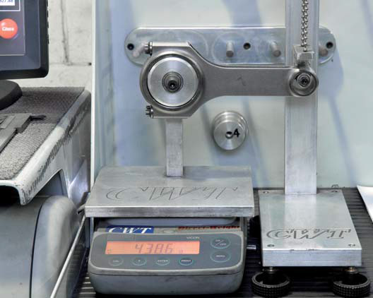 |
This special fixture is used to accurately weigh the big end of the rod. |
|
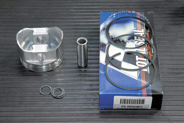 |
These components, plus half the weight of the conrod, combine to make up the reciprocating weight. |
|
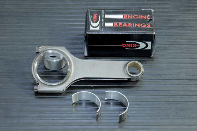 |
The rod and bearing shells, plus a small allowance for oil, make up the rotating weight. |
|
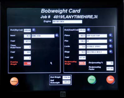 |
This screen shot shows all the data input to calculate the bobweight. |
When calculating the final bob-weight figure only a percentage of the reciprocating weight is used, depending on the type of engine and its intended application. In this case the figure is 50%, so the reciprocating weight used in the calculation is 413.65 grams. So our total bob-weight value per cylinder is 891.15 grams. Now remember that a typical V8 has two rods and pistons sitting side-by-side on each conrod journal, so there is actually twice the amount of weight attached to each pin. David muliplies the calculated 'per cylinder' value by 2 to arrive at a total of 1786.30 grams. This is called the bob-weight and is the total weight that will be bolted to each of the four big end journals during the dynamic balancing process, to simulate the weight of the rods, pistons and other hardware.
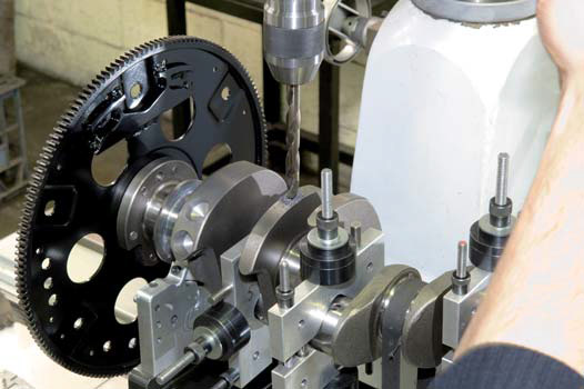
Now that the bob-weight has been determined, the crankshaft can be positioned on the nylon had bearings of the balancing machine. As this 383 is externally balanced, the flex plate and the harmonic balancer are also fitted to the assembly as their balancing weights dramatically affect the balance of the crank.
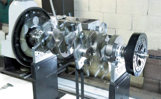 |
The crankshaft is spun up a number of times during the balancing process |
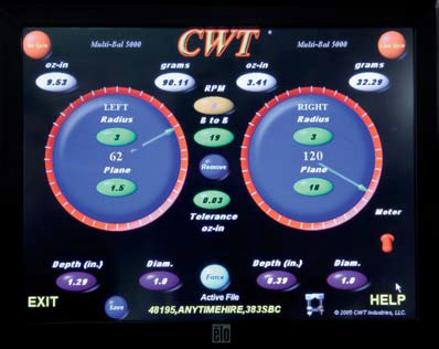
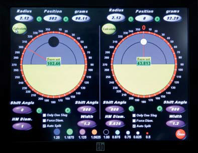
A soft belt drive spins the crankshaft through a preliminary test cycle to determine how much the crank is out of balance at the rea (referred to as left in the software) and at the front (right). In this case, the first spin revealed that the crank was 90.11 grams out on the left and 32.29 grams out on the right. The index information allows the crank to be rotated by hand until the exact point of imbalance is at 12 o'clock to enable the counterweight to be drilled with ease.
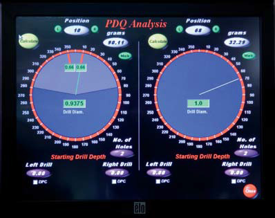 |
The two red lines on the left-hand dial show the points where holes are to be drilled in the rear counterweight. |
|
 |
After the first spin, the left (rear) of the crank is 90.11 grams out and the right (front) is 32.29 grams out. |
The actual drilling of the holes is done in stages to ensure that the exact amount of material is removed and no more. Drilling a little and then re-testing ensures accuracy. After two steps, the first of the rear holes was drilled to the right depth and the pilot of the second was also drilled. Half the second hole was then drilled before another spin up to make sure all was well. Then the front hole was started (to remove 32.29gm). Things were looking good so the second rear hole was drilled to depth with the built-in drill press, followed by the front hole to the full depth. After re-checking the balance yet again, there were a few grams left to remove before the crank would be balanced within tolerance. This time the front and rear holes needed to be in a different location and due to the position of the front and rear counterweights on the crank, this was not possible. This was not a problem though because David simply chose a smaller diameter drill bit and made a small hole in the next counterweight along - front and rear.
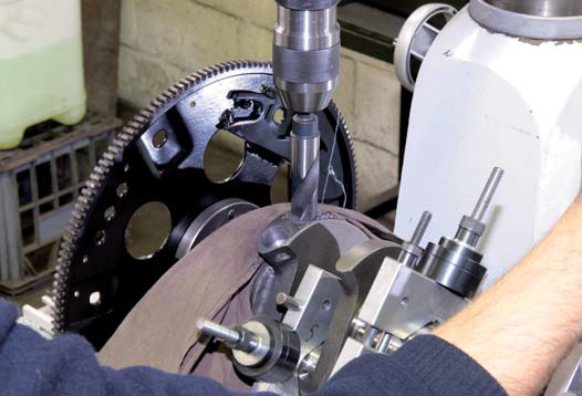 |
One hole has already been drilled in the rear counterweight and David is part way through the second one. |
|
 |
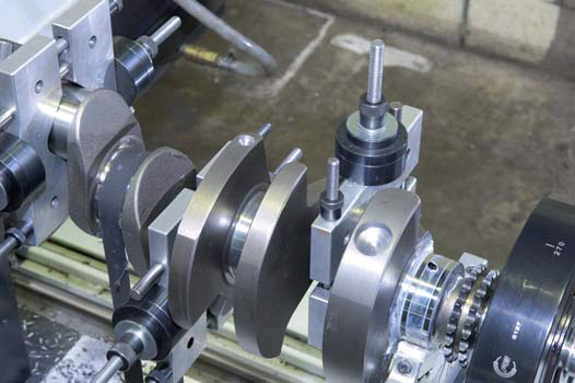
A smaller second hole in the next counterweight finalises balance at the rear of the crank. |
|
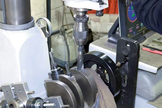 |
Once the rear of the crank is approaching balance, the front can be drilled for correct overall balance. |
|
 |
A second hole is also needed at the front of the crank to bring things within tolerance. |
|
 |
Although not required in this engine, this screen shot shows the software's ability to position heavy metal slugs if needed for balance. |
Now that the crankshaft has been fully balanced, it can be treated with a corrosion inhibitor and packed, along with the rods, pistons, flex plate and harmonic balancer, ready for the owner to collect.
The process, physics and mathematics involved in balancing a crankshaft are very complex but it does not take a genius to recognise that with hundreds or even thousands of pounds of force generated by an out of balance crankshaft, there is no choice but to balance it and the other rotating and reciprocating assembly, to free up power and ensure smooth running and long life.
With the right equipment, the crankshaft in your new or rebuilt engine can spin freely and you do not have to worry about bolts continually coming loose or regular trips to the dentist for lost fillings!
Internally balanced refers to an engine that can be balanced without the need for 'external' weight attached to the harmonic balancer or flexplate/flywheel. Externally balanced engines have extra weight attached to these parts. Why is this the case? One reason is that the orginal vehicle manufacturer needs to increase the capacity of an existing engine design, a longer stroke and a larger bore equals more torque and power - cheaply. An example of this is the small block Chev. Originally designed to be no more than 283 CID; it was eventually stretched to 400 CID, which meant that there was just no more room inside the crank case for extra counter weight. So, the cheapest and easiest option for GM was to fix external weights to the harmonic balancer and flywheel/flexplate, hence the name external balance.
Galloway Engines would like to acknowledge and thank Perth Street Car for the use of the information in their "Spin Doctors" article.